A Report on
Stair climbing mechanism
The Scepter
Submitted by
Subhasis Behera (002120169)
Under the guidance of
Dr. Rakesh Chandra,
HOD, Department of Mechanical Engineering.

Dr. B. R. Ambedkar National Institute of Technology, Jalandhar,
ACKNOWLEDGEMENTS
We would like to express my sincere thanks to our Project Guide, Dr. Rakesh Chandra, Professor, Head, Dept. of Mechanical Engg., National Institute of Technology, Jalandhar for his guidance and encouragement throughout the project.
We are really thankful to Mr. Promod Kumar, Mr. M. K. Tiwari, and Mr.
Raman Bedi, Professors, Mechanical Engg. Dept. for their continuous support
during this work.
We also extend heartfelt gratitude to all those who helped us for the successful construction of the model.
INDEX
i
ii
Front Page
……………………………………………………………………...........
iii
Acknowledgements
………………………………………………………………….
1
Index
………………………………………………………………………………...
2
Abstract ……………………………………………………………………………..
7
1 Introduction
………………………………………………………………………
12
2 Design & Construction
……………………………………………………………
18
3 Kinematic Analysis
……………………………………………………………….
21
4 Modeling & Animation
……………………………………………………..
a
5 Conclusions
…………………………………………………….. ……………….
References …………………………………………………………………………...
ABSTRACT
Walking machines are advanced alternatives to wheeled locomotion which find applications where wheeled systems cannot be operated. Of these, Stair-climbing machines have come out to be the field, to have been revolutionized in the recent past. Basic purpose of these machines remains serving the handicapped which becomes the objective of the model demonstrated in this paper.
The paper is about an Experimental model of a Stair-climbing Mechanism – The scepter, which was designed and constructed by me in Dr.B.R.Ambedkar National Institute of Technology, Jalandhar. The paper demonstrates the construction and kinematics analysis of the model and its drafting in AutoCad 2002.
The model has also been designed and animated in two softwares - ‘Pro Desktop Express – the desktop version of Pro Engineer’ and Solid Edge. However Pro Desktop was effective of the two and so animation in that application has been presented.
The mechanism is basically a modification of the 3-dimensional slider crank mechanism and is composed of a structure made of wood and the kinematic chain is constituted by a sequence of wooden links whose prime mover is connected to a 3 W A.C. motor. The motion analysis has been initiated with its calculation of Degree of freedom and checking the customized constrains.
The success of the model would be realized when the dynamic force analysis of the model is completed and the stability established in the original model which would follow as our next work.
CHAPTER 1
INTRODUCTION
1.1 Walking Machines
One need only watch a few slow-motion instant replays on the sports channels to be amazed by the variety and complexity of ways a human can carry, swing, toss, glide, and otherwise propel his body through space. Orientation, balance, and control are maintained at all the times without apparent effort, while the ball is dunked, the bar is jumped, or the base is stolen, and such spectacular performance is not confined to the sports arena-behavior observable at any local playground is equally impressive from a mechanical engineering, sensory motor integration point of view. The final wonder comes when we observe the one year old infant’s wobbly with the knowledge that running and jumping will soon be learned and added to the repertoire.
Walking
machines are the advanced alternatives to the
wheeled locomotion systems which
find applications where wheeled
systems cannot operate. Some instances are
in hauling loads
over soft or
irregular ground often with
obstacles , agricultural operations
, for movements in situations designed
for human legs
such as climbing stairs , ladders …..
To carry out these operations
numerous walking machines have been developed.
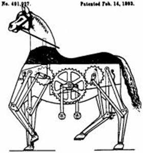
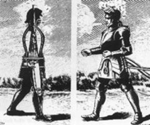
Fig. Some of the first walking
mechanisms
1.1.1
Human – Walking machines analogy
Two-legged walking, running, jumping and skipping are some of the most sophisticated movements that occur in Nature, because the feet are quiet small and the balance at all times has to be dynamic; even standing still requires sophisticated control. If one falls asleep on ones feet he falls over.
The human stabilizes the movement by integrating signals from:
- Vision which includes ground position and estimates of the firmness of the ground and the coefficient of friction.
- Proprioception that is knowledge of the positions of all the interacting muscles, the forces on them and the rate of movement of the joints.
- The vestibular apparatus, the semi-circular canals used for orientation and balance.
A very large number of muscles are used in a coordinated way to swing legs and the muscle in an engine consisting of a power source in series with an elastic connection. The muscle activity is pulsed and there is an energetically optimal walking speed of 3.5 km/hr when the legs swing in a natural oscillation frequency, although they can swing much faster without much extra loss of energy. Various walking machines have been developed to imitate human legs, but none is as efficient as those of humans.
1.1.2 Classification of Walking Machines
Walking machines are
classified according to the numbers of legs or limbs they constitute. They
range from single-legged hopping mechanisms to
They may be
· One-legged
· Two-legged
· Three-legged
· Four-legged
· Six-legged
· Eight-legged
1.1.3 Design aspects
Three important aspects in the design of any walking mechanism
·
Orientation
·
Balance
·
Control
Each of these aspects has to be well controlled for the success of any new design of walking mechanism.
1.2 Stair Climbing
Mechanism
Stair Climbing
mechanisms are walking machines which have specific target of climbing stairs.
Stair Climbing Mechanisms are various and diverse in the mechanisms they are
based on.
 Dr.
Dean Kamen, Founder of FIRST and the President and owner of DEKA Research &
Development Corporation, a Manchester, New Hampshire-based company specializing
in advanced technologies in medical equipment, is the man who recently
revolutionized the field of Stair Climbing mechanisms after he came up with iBOT, a stair-climbing robotic
wheelchair
Dr.
Dean Kamen, Founder of FIRST and the President and owner of DEKA Research &
Development Corporation, a Manchester, New Hampshire-based company specializing
in advanced technologies in medical equipment, is the man who recently
revolutionized the field of Stair Climbing mechanisms after he came up with iBOT, a stair-climbing robotic
wheelchair
The speciality of iBOT is that the mechanism on which it is based is dynamically stable. Dynamic stability is what every Robotic engineer dreams for in his robot. And that is why the machine has climbed such success.
1.3 The Scepter
‘Scepter’
literally means a device which is used by the disabled people. The Scepter’ –
name of the Stair Climbing Mechanism designed by us was named so because of the
fact that its basic purpose is to aid the disabled. The design, construction,
analysis, modeling, animation of the model are discussed in the following
chapters.
DESIGN & CONSTRUCTION
2.1 Design Introduction
The scepter is a small mechanical system which can walk in a straight path as well as can climb stairs while maintaining static balance all the time. It walks with the help of its two front legs and two wheels. It can climb in stairs up to 2cm. the model is not optimized and moreover the power of the small motor is also another limiting factor. These limiting factors together result in the small height of climb. The small speed is due to the small rpm of the motor used. For legs instead of two can also be used. The model is only an experimental model and shows the basic mechanism. A number of improvements are under development. The final model will be used as a stair climbing wheelchair. The features of the final model will be discussed later.
2.2 Description
The different parts of the system are
· Front-legs
· Frame
· Wheels
· Prime mover (electric motor)
· Chain
· Leg aligner link
· Motion transmitting cam
The function of each part is being discussed as follows.
2.3 Front legs
The front legs of the model are made of aluminum to keep the net weight and mass moment of inertia low. The legs are L shaped, so as to counter the longitudinal moment produced by the weight of the system. It actually serves the purpose of two legs. Four front legs can also be used instead of two L-shaped legs. As at any moment two wheels and only one leg is in touch with the ground the legs have to be L-shaped to ensure the stability of the system.
In the future steering of the system will also be done on the front legs themselves. The legs will also be provided with vacuum suction so as to ensure firm hold on the ground.
 ` While climbing the front legs carry
the entire horizontal load. This load is carried by friction in the legs. To
decrease this required friction, the rear wheels has also to be powered independently.
The power will be provided only when necessary, i.e. when the wheel encounters
a stair or a hurdle. This is another development that is under
consideration.
` While climbing the front legs carry
the entire horizontal load. This load is carried by friction in the legs. To
decrease this required friction, the rear wheels has also to be powered independently.
The power will be provided only when necessary, i.e. when the wheel encounters
a stair or a hurdle. This is another development that is under
consideration.
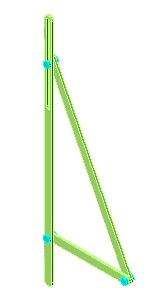
2.4 Frame
The frame is made of wood. It has to resist the entire load and transmit the power. If the frame wouldn’t be rigid enough, it will deform due to the torque provided by the motor (which actually happened in my first model, which was made of cardboard. So I had to provide wooden beams so as to resist the bending load). When the frame is not rigid enough it itself deforms instead of transmitting the motion. But the frame should be light besides being rigid. So the choice of material is crucial here. The material should be rigid as well as light. As the frame contributes maximum to the weight of the entire system it should be optimized in terms of utilization of material. The structure of the frame should resist the load most economically, i.e. only those parts should be most rigid which are under more loads. The stress analysis can yield the desired value for the rigidity of the section under consideration, which is to be done in future.
2.5 Wheels
The wheels are also made of wood. They too share the load of the system. The wheels should have been rimmed instead of discs. The moment of inertia of the wheels should be kept low, so as to keep the required torque low. But due to the non-availability of such small sized rimmed wheels disc shaped wheels are used. It is also the ease of manufacture and mounting of disc shaped wheels that they have been used as wheels. This resulted in the lowering of the maximum efficiency of the system, i.e. the maximum height that could have been climbed is reduced.
While climbing a stair the vertical load is balanced by the friction on the wheels. So the coefficient of friction between the edge of the stair and the wheels has to be sufficient enough so as to balance the vertical load. But there is a limit to the value of the coefficient of friction. So the load that can be carried by them has a limit. The problem can be solved by decreasing the load that is to be carried by the wheels. This can be done by shifting the center of gravity towards the front. That can be done by moving the seat of the wheelchair towards the front. That is the development to be done in the future.
2.6 Prime mover
This is a 3 watt and 240 volts electric motor. The rpm of the motor is between 5 and 6. This lightweight and powerful motor is the only source of power. The power is transmitted through a chain. A bush is mounted on the motor which is the link between the motor and the chain. The motor is actually used in the automatic swing attachment in desert coolers. The chain is used in the engine case of Hero Honda motorcycle.
2.7 Leg-aligner link
This link is used to align the legs, i.e. this ling is used in order to keep the degrees of freedom of the system one. The leg aligner is mounted on the structure.
2.8 Motion transmitter cam
 This
is the most important part of the system. This link changes the circular motion
provided by the motor to leg like motion.
This
is the most important part of the system. This link changes the circular motion
provided by the motor to leg like motion.
CHAPTER 3
KINEMATIC ANALYSIS
3.1 Two-Dimensional Equivalent Mechanisms
 For the kinematic analysis to begin
the best 2-D equivalent or planar form of the mechanism has to be identified.
For the kinematic analysis to begin
the best 2-D equivalent or planar form of the mechanism has to be identified.
A
static 2D Equivalent is shown in fig.10
One
of the forms can be fig.9. This would be a dynamic mechanism, i .e, none of the
links is made fixed and so the entire system would be in motion. So this is the
representation of the actual motion exhibited by the scepter. But analysis of a
dynamic mechanism would be much more complicated than that of static one.
Fig.9 is a two-dimensional representation of the actual mechanism. This mechanism shows the motion of one leg and one wheel. The link a represents the cam (motion transmitter), which initiates the motion. The link a i.e., the cam is given the motion. So it is constrained to move in a particular direction.
The link b is the leg. The point 2 is the leg aligner. It is the part of the structure and this guides the leg while in motion. The kinematic pair between the leg, i.e. a slotted lever and this leg aligner is a higher pair.
The point 4 is the contact point between the wheel and the ground. This is also represented by a slotted leaver link, again a higher pair. As there is no slip between the wheel and the ground, this can be taken as a link while modeling the system in two dimensions.
The point 3 is the contact between the legs and the ground. Again there is no slip between the legs and the ground and hence it was possible to model that as a lower pair.
The link d is the structure and link c is the ground. Thus in total there are 4 links. There should be 5 kinematic pair, out of which 3 are lower and 2 are higher. The details of these kinematic pair are given below.
Between link d and a (frame and cam): lower pair
Between link a and b (cam and leg): lower pair
Between link b and c (leg and ground): lower pair
Between link b and d (leg and leg aligner): higher pair
Between link c and d (ground and wheel): higher pair
The degree of freedom of the system is = 3(4-1)-2*3-2 = 1
As the degree of freedom is found to be 1 the motion is clearly constrained.
The following sections demonstrate the derivation of the velocity and the accelerations expressions for the mechanism.
3.2 Velocity
Equations
Fig.11 Displacement Diagram
From the geometry of the figure;
r2 = r1
+ r21
⇒r2eiɵ2 = r1eiɵ1 + r21eiɵ21 … … … … … … … … … (1)
So differentiating the above geometric
expression yields
0 = iɵ̇1r1eiɵ1 + iɵ̇1r21eiɵ2 1 + r ̇21eiɵ2 1 … … … … … … … (2)
Now, this equation can be rewritten in trigonometric form as:
0 = r1ɵ̇1(icosɵ1- sinɵ1) + r21ɵ̇̇21(icosɵ21 - sinɵ21) + r ̇21(cosɵ21 + isinɵ21) … … … (3)
By
equating real and imaginary parts,
0 = -r1ɵ̇1sinɵ1 + r ̇21cosɵ21 – r21ɵ̇21sinɵ21
0 = r1ɵ̇1cosɵ1 + r21 ɵ̇̇21cosɵ21 – r ̇21sinɵ21
The
unknowns of these equations are r
̇21 and ɵ̇̇21. These can be deduced by solving the two
equations.
Again
from the geometry of the figure:
R4
= r43 + r32 + r2
⇒ r4eiɵ4 = r43eiɵ4 3 + r32eiɵ 3 2 + r2eiɵ2
Differentiating
the above geometric expression yields,
0 = r ̇43eiɵ4 3 + i r43ɵ̇43eiɵ43 + r ̇32eiɵ3 2 + iɵ̇32r32eiɵ3 2
This equation can be rewritten in trigonometric form as:
0 = r ̇43 [cosɵ43 + isinɵ43] + r43ɵ̇43 [icosɵ43- sinɵ43] + r32ɵ̇32 [icosɵ32 - sinɵ32]
+ r ̇32[cosɵ32 + isinɵ32]
By equating real and imaginary parts,
0 = r ̇43cosɵ43 - r43ɵ̇43sinɵ43 - r32ɵ̇32sinɵ43 + r ̇32cosɵ32
0 = r ̇43sinɵ43 + r43ɵ̇43cosɵ43 + r32ɵ̇32cosɵ43 + r ̇32sinɵ32
The unknowns of the equation are r ̇43 and ɵ̇43.
As ɵ̇32 = -ɵ̇̇21
and r ̇32 = - r ̇21, the unknowns can be deduced by solving the
two equations.
3.3
Acceleration Equations
The accelerations can be obtained by differentiating the velocity expressions. The results are:
0 = ir1ɵ̈1eiɵ1
– (ɵ̇1)2r1eiɵ1 +
ir21ɵ̈21eiɵ2 1
+ r ̈21eiɵ2 1
+ (ɵ̇1)2
r21eiɵ2 1 + iɵ̇̇21 r ̇21eiɵ2 1
(∵ɵ̈1 = 0, for simplicity)
0 = – (ɵ̇1)2r1eiɵ1 +
ir21ɵ̈21eiɵ2 1
+ r ̈21eiɵ2 1
+ (ɵ̇1)2
r21eiɵ2 1 + iɵ̇̇21 r ̇21eiɵ2 1
This equation can be rewritten in
trigonometric form as:
0 = r ̈21 [cosɵ21 + isinɵ21] – r1 (ɵ̇1)2[cosɵ1+ isinɵ1] + r21ɵ̈21 [icosɵ21 - sinɵ21] - (ɵ̇1)2 r21 [cosɵ21 + isinɵ21] + ɵ̇̇21 r ̇21 [icosɵ21 - sinɵ21]
By equating real and imaginary parts,
0 = r ̈21cosɵ21 – r1 (ɵ̇1)2cosɵ1- r21ɵ̈21sinɵ21-(ɵ̇1)2r21cosɵ21 - ɵ̇̇21 r ̇21sinɵ21
0 = r ̈21sinɵ21 – r1 (ɵ̇1)2sinɵ1 + r21ɵ̈21cosɵ21 + (ɵ̇1)2r21sinɵ21 + ɵ̇̇21 r ̇21cosɵ21
The unknowns of the equation are r ̈21 and ɵ̈21
. Solving the 2 equations we can find
the unknowns.
Differentiating the second velocity
expression, we have:
0 = r ̈43eiɵ43
+ ir43ɵ̈43eiɵ43
– (ɵ43̇) 2r43eiɵ43
+ iɵ̇̇43r ̇43eiɵ32 +
ir32ɵ̈32eiɵ3 2
+ r ̈32eiɵ2 1 - (ɵ̇32)2
r32eiɵ3 2 + iɵ̇̇32r ̇32eiɵ3 2
Writing in the trigonometric form,
0 = r ̈43[cosɵ43 + isinɵ43] + r43ɵ̈43[icosɵ43- sinɵ43] – (ɵ43̇)2r43[cosɵ43 + isinɵ43] + ɵ̇̇43r ̇43 [icosɵ43- sinɵ43] + r32ɵ̈32[icosɵ32 - sinɵ32]+ r ̈32[cosɵ32 + isinɵ32] -(ɵ̇32)2 r32[cosɵ32 + isinɵ32]+ ɵ̇̇32r ̇32[icosɵ32 - sinɵ32]
By equating real and imaginary parts,
0
= r ̈43cosɵ43 - r43ɵ̈43 sinɵ43 – (ɵ43̇)2 r43cosɵ43 - ɵ̇̇43r ̇43 sinɵ43- r32ɵ̈32sinɵ32+ r ̈32cosɵ32
- (ɵ̇32)2r32cosɵ32 - ɵ̇̇32r ̇32sinɵ32
0
= r ̈43sinɵ43 + r43ɵ̈43 cosɵ43 – (ɵ43̇)2 r43sinɵ43 + ɵ̇̇43r ̇43 cosɵ43 + r32ɵ̈32cosɵ32+ r ̈32sinɵ32 - (ɵ̇32)2r32sinɵ32 + ɵ̇̇32r ̇32cosɵ32
The unknowns of the equation are ɵ̈43 and r ̈43.
Solving the 2 equations we can
find their values.
(∵ ɵ̈32 =
- ɵ̈21,
and r ̈32 = -
r ̈21)
Thus we can
find the velocities and accelerations at any point in the mechanism.
CHAPTER 4
MODELLING & ANIMATION
4.1 Methodology
The methodology for modeling and animation of the mechanism:
- Model the parts of the model
- Assemble them
- Define the grounded link
- Define constrains between the mating parts
- Define motion to the parts
- Create frames for different positions of the model sequentially
- Save as an *.avi or *.mpg file
4.2 Softwares used
The animation has been done in two softwares.
- Pro Desktop Express
- Solid Edge
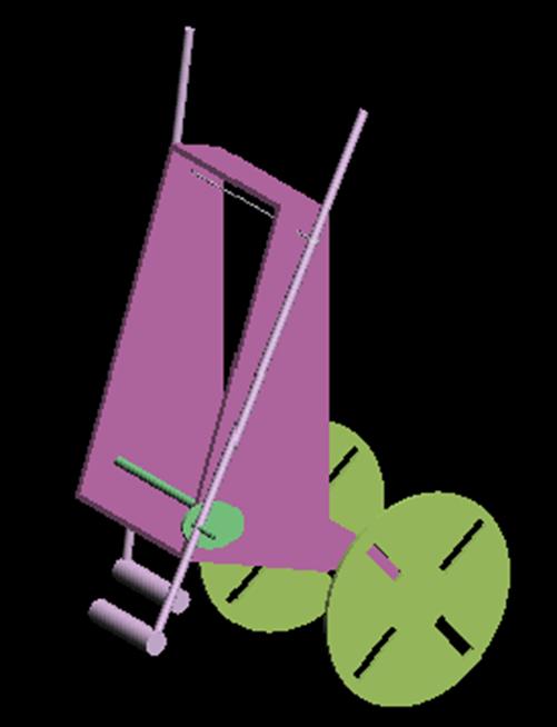
But only the work done in Pro Desktop Express is presented. (fig.12)
Fig.12 Model
animated in Pro Desktop Express
CHAPTER 5
CONCLUSIONS
5.1 Result
After numerous demonstrations and trials, the maximum height of the stairs, ‘The Scepter’ can climb is standardized at 4cms
5.1 Limitations
·
Power of the motor insufficient to lift the
structure.
·
Moment of Inertia of the wheel is high since
it’s an wooden disk. It should have been a circular ring.
·
Friction at the contacts of the legs with the
surface is not optimum.
·
Friction at the joints is also quite high since
it’s a wooden system.
5.2 Future Scope
· Steering mechanism: a slider crank mechanism at the feet to offset the contact with the surface.
· Self-defined ellipse system:
v An hydraulic or an pneumatic system to be used to vary the major and minor axes
v Sensors can be used to decide determine the dimensions of the stairs to be climbed.
· Vacuum contact system at the legs
· Sensors to stimulate all the above mechanisms automatically
· Powering the rear wheels
· Horizontally maintained seat (here base plate)
REFERENCES
Web sites
·
http://www.neuroprosthesis.org/dkamen.htm
·
http://ls11-www.cs.uni-dortmund.de/people/ziegler/RoboterLaufen2Legs.html
·
http://www-personal.engin.umich.edu/passive_walking.html
Books
·
Dynamics
of Machines – Henry J. Sneck
·
Kinematic
Analysis and Synthesis – Jack T. Kimbrell
·
Design
of Mechanisms - Norton
·
Theory of Machines – Shigley
·
Robots and Telechirs – W.
H. Thring
·
Computer Aided Design – Kaplinsky